Sheet Metal
Approximate Development
There are only two types of surfaces in metal fabrication - 'Elementary' and 'Warped'.
Elementary Surfaces:
To qualify to be an Elementary surfaces a 'Straight Edge' must make contact along the totality of the surface at a given location. This contact line is called an 'Element' of that surface.
When creating objects from Sheet material there are only three surfaces configerations that meet this standard.
· Flat Surfaces (Figure I) which lie on a single Plane.
· Curved surfaces (Figure II) such as sections of a Cylinder.
· Radial Surfaces s (Figure III) such as Sections of a Cones.
Sheet-metal objects fabricated from any combinations of these three types of surfaces can be developed accurately onto a single plane and formed back to their original three-dimensional form by simple folding and rolling techniques without stretching or compressing the material.
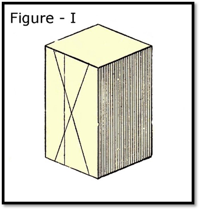
Lines drawn on a Flat surface, (Figure I) are always 'Elements', since they are in full contact with the surface.
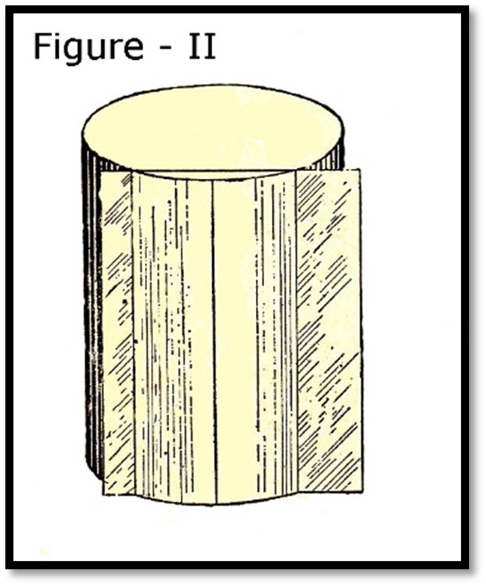
A Curved surface (Figure II) is a surface where no three consecutive parallel 'Elements' are on the same plane. To be an 'Element' of a curved surface it is required to be in full contact with the surface.
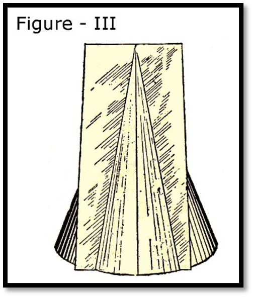
A Radial surface (Figure III) is again a surface where no three consecutive radial 'Elements' lie in the same plane. To be an 'Elements' of a surface radiating from an apex it is required to be in full contact with the surface.
Any Sheetmetal or Plate fabrication composed of any combinations of these surfaces can be developed accurately onto a single plane. This includes such 'Fabrications' as Single, Double, and Multi-Chined metal and plywood boat hulls.
For sheet-metal and plate objects consisting of all Plane surfaces mathematical formula's such as 'Bend Allowance' and 'Bend Deduction' are used to 'Unfold' the fabrication onto a single Plane. Full details can be found in my book, 'Applied Metal Boatbuilding Methods - Sheetmetal Pattern Development'.
For sheet-metal and plate objects
that are a combination of Elementary Planes, Curves, and Radial 'Elements'
layout methods know as Triangulation, Parallel Line development, and Radial
Line development are used to 'Unfold' the fabrication onto a single Plane.
Warped Surfaces:
A warped surface has no 'Elements'. It is a surface where a straight edge makes contact at a single point only. A Sphere (Figure IV) is a good example of a surface that cannot be 'Unfolded' 100% accurately onto a single plane. However, such a surface can be developed 'Approximately' to lie on a single plane.
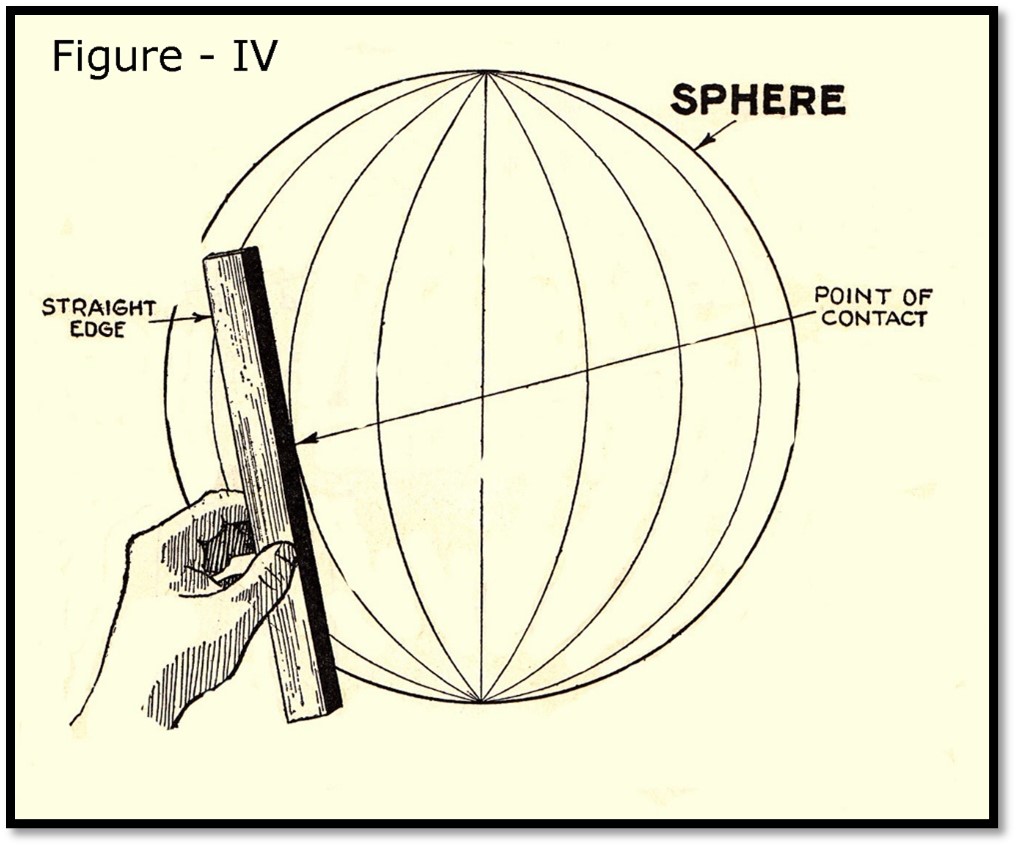
The Sphere is a good place to begin to understand how Approximate development works, since it is a symmetrical object where only one pattern is required as compared to the many patterns required to 'Unfold' the warped surface of a true round metal boat hull.
Since 'Approximate' can be a relative term, a plan view of two (2) twelve-inch (12") spheres (Figure V) are shown cut at their diameters. One Sphere will be divided into eight (8) chords-segments and the other into sixteen (16) chords-segments. The chord line represent the segment of the Sheet-metal sphere developed 'Approximately' onto a single plane.
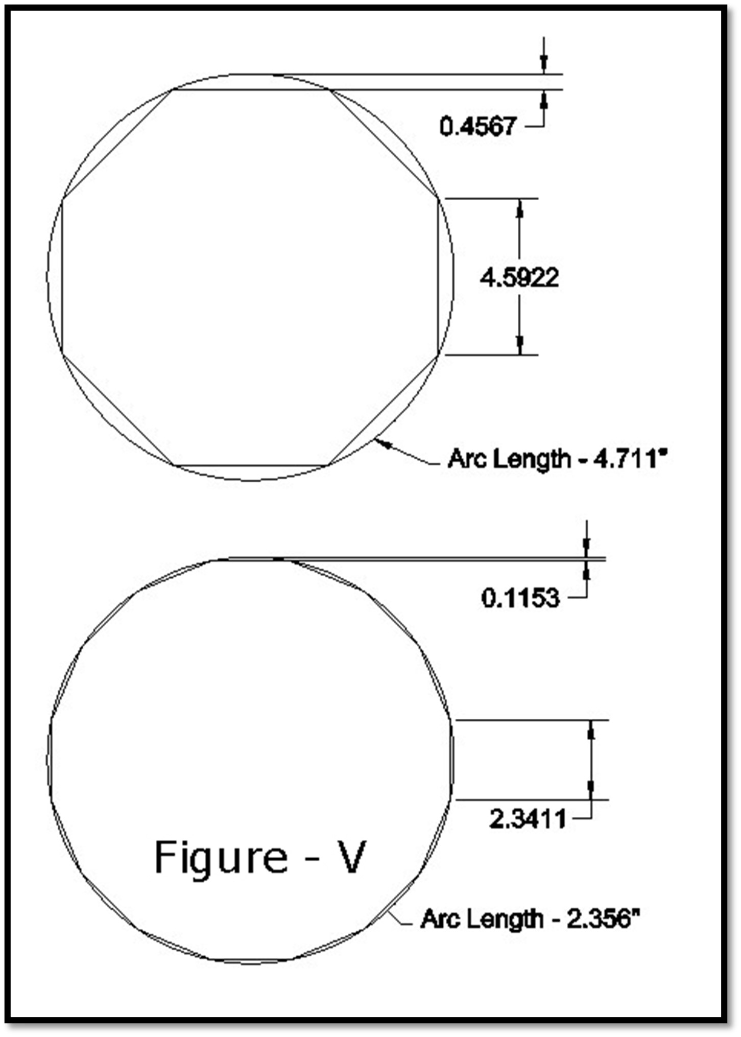
We could have divided the sphere into even more chords-segments, say thirty-two (32) or even sixty-four (64) or any amount we desire. Nevertheless, the eight (8) and sixteen (16) chord arrangements will adequately describe the theory of Approximate development for Warped or Compound surfaces.
(Figure VI) illustrates the Eight (8) approximately developed chords-segment layout 'Unfolded' onto a single plane using 'Parallel Line Development'.
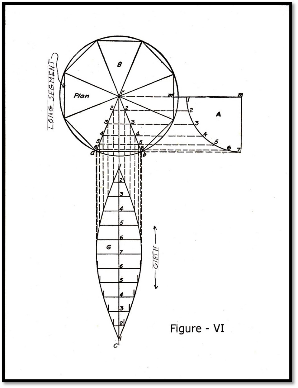
In this eight-segment layout the chord length is 4.592", the distance between the chord and the finished surface arc of the sphere is 0.456", and the arc length of the finished surface of the sphere is 4.711". The difference in length between the chord length and the arc length is 0.199". The sphere therefore has been 'Approximately' developed. When assembled the eight (8) segment sphere would be very prismatic in form.
The sixteen (16) segment sphere, however, would be less prismatic in form. In the sixteen (16) segment layout the chord length is 2.341", the distance between the chord and the finished surface arc of the sphere is 0.115", while the arc length at the finish surface of the sphere is 2.356". The difference in length between the chord length and the arc length is now 0.015".
The 'End User' could accept the eight-sided sphere for the top of their roof final or they could opt for the sixteen-sided version which brings the fabrication closer to the true surface of the sphere.
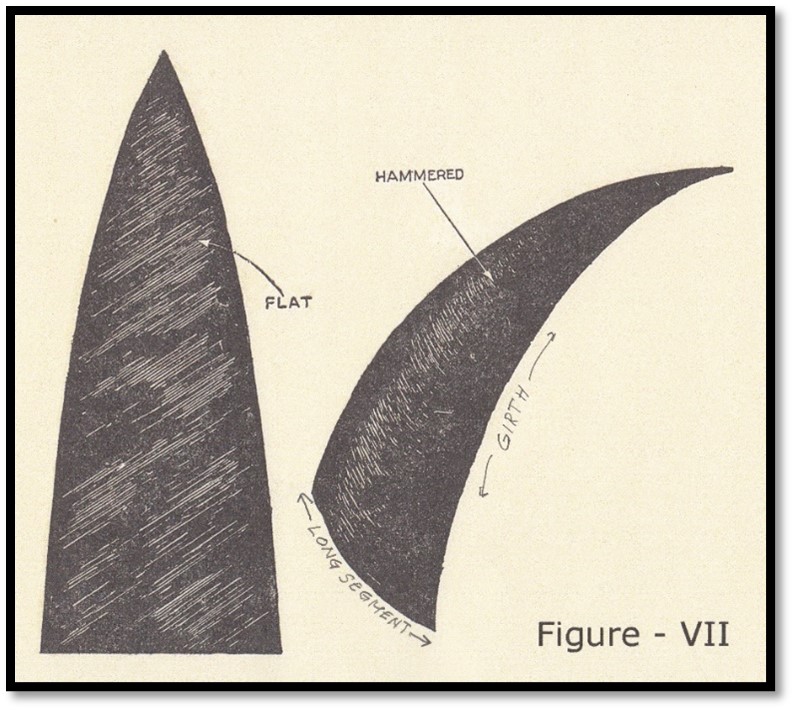
If neither of the above were acceptable a peening or hammering process would be
required to stretch the material to its true shape as seen in (Figure
VII). It should be apparent that
the eight (8) segment version would require more peening, but have less seams,
while the (16) segment version would require less peening, than again there are
more seams.
Appling Approximate Development of Shell Plating of a True Round Boat hull:
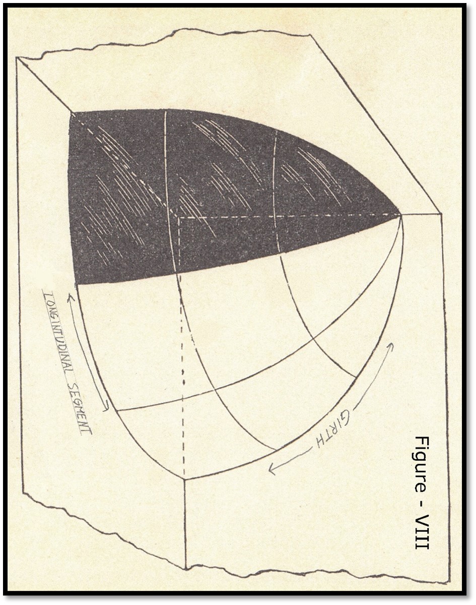
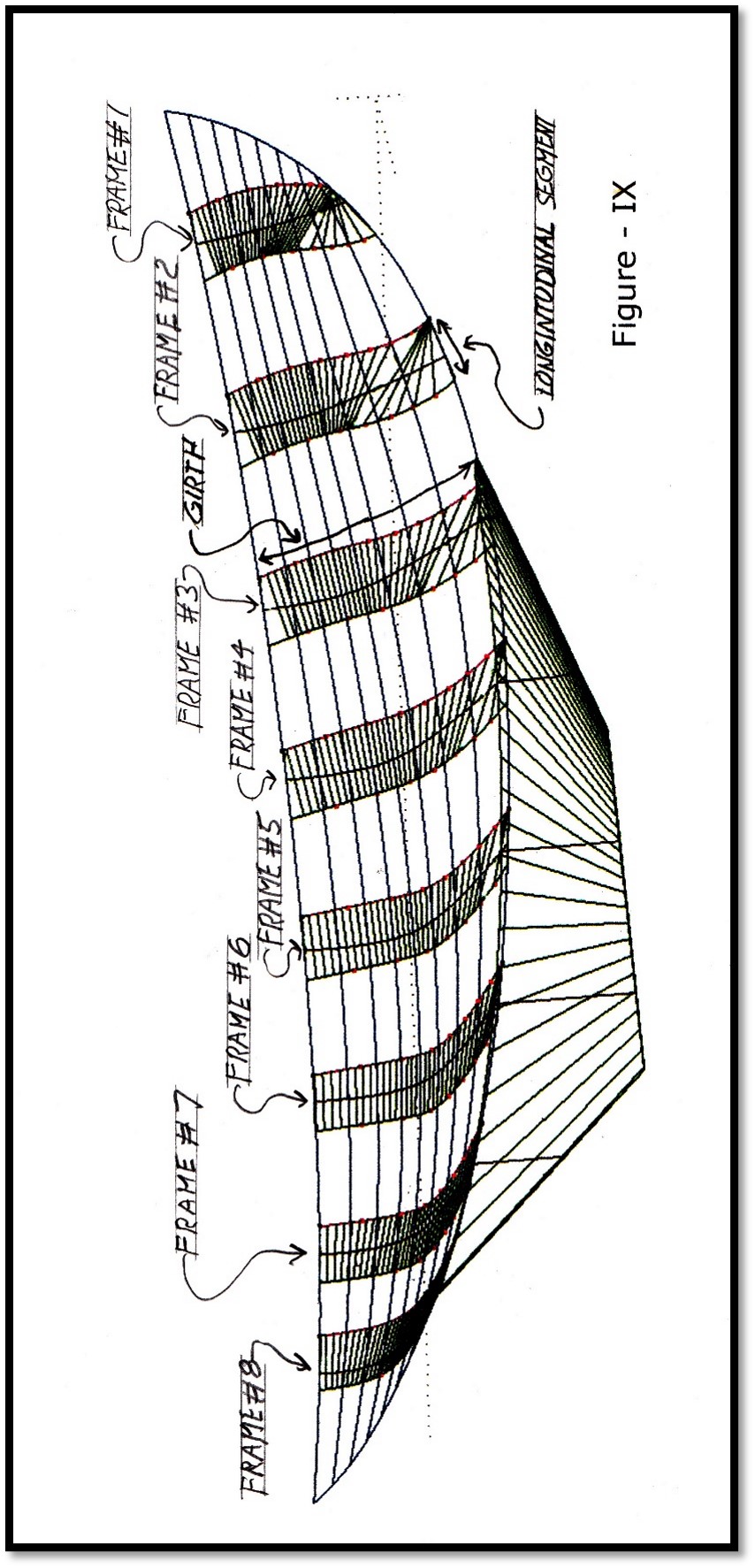
Before proceeding to 'Unfolding' the Warped surfaces of a True Round Metal boat hull, we need to relate the terms 'Girth' and 'Length' used in hull design to the Sphere in (Figure VIII) to relate the two vastly different 'Fabrications' to each other.
The only real difference between the two objects is that the Sphere needs only a single 'Approximately' developed pattern to define every segment of the sphere in both 'Girth' and 'Length'. Whereas the numerous segments that makeup the surface of a true round hull need to be developed individually since the 'Girth' and 'Length' vary at every longitudinal segment of the hulls shell plating.
The surface of the hull in (Figure IX) has been divided into twenty-three (23) sub-surface segments along the length of the hull, which corresponds to the segments use to divide the Sphere. For clarity, only the sub-surface segments that coincide with a transverse frame are shown. There are however two sub-surface plating segments between the one's shown.
Longitudinal Direction of Roll:
Just as the Sphere was divided into chords at its diameter the free-formed curve (Figure X) of the Sheer-Line, shown in 'Plan View', is used to illustrate the chords along the length of the hull. The freeform curve represents the true form of the 'sheer-line', while the chord- segments represent the 'Approximately' developed prismatic 'Sheer-line' required for 'Approximate Metal Fabrication'. The nodes represent the end-points of each chord-segment.
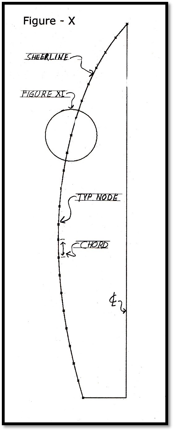
The length of this chord detailed in (Figure XI) is 8.681". The length of the curve is 8.687". The difference being 0.006". The distance at the centerline of the chord to the free-formed 'Sheer-line' is 0.047". In your mind’s eye, visualize how close the approximately development surface is the curved surface.
Looking at the 'Approximate' developments numbers, are you really going to take a hammer to this shell plate in an attempt to stretch the plate from 8.681" to 8.687" by 0.006”. I, personally do not think so.
I believe that the best approach would be to apply a thin coat of fairing compound to the hull over beating the shell plating with a hammer. But that is only me.
The chords dividing up the length of the hull represent only one direction of roll. Next the other direction of roll - 'Girth'.

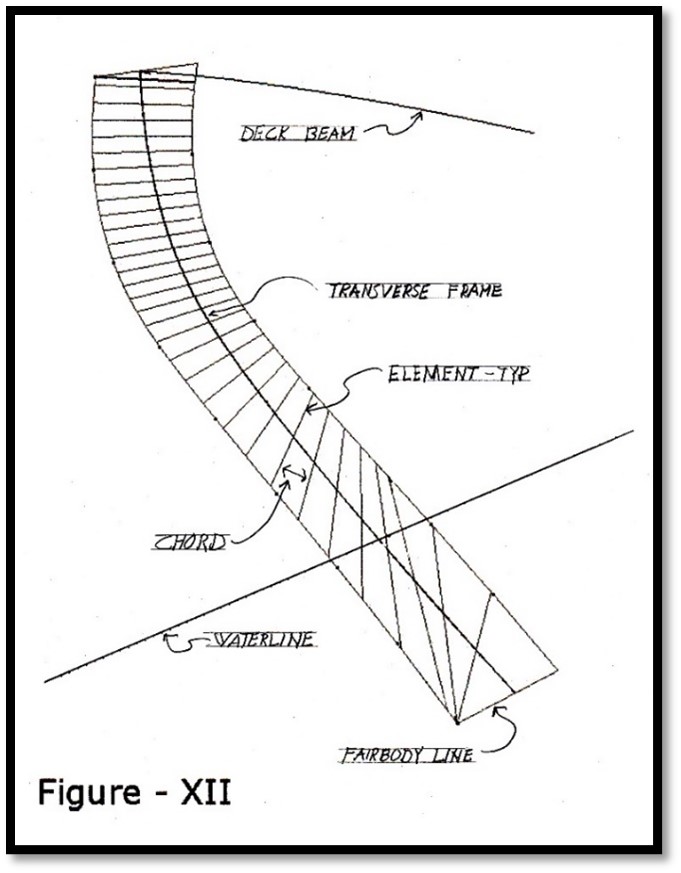
The Roll in Girth:
The same basic principle of 'Approximate' development previously discussed along the length of the hull applies in 'Girth'.
(Figure
XII)
illustrates a single longitudinal chord-segment-surface that is
located at a transverse frame in a three-dimensional view.
The cross lines are 'Elements' of the surface, that is a straight edge would be in full contact with the surface along this line. The area between the 'Elements' can be compared to the 'Chords' that divided the hull longitudinally.
The only difference is that the roll along the length of the hull is accomplished by welding individual 'Chord-Segments' together, while the roll along the 'Girth' is accomplished by forming the material along the 'Elements' in a Press-Break.
|
|
|
|
 |
 |
|
|
|
|
|
|